-40%
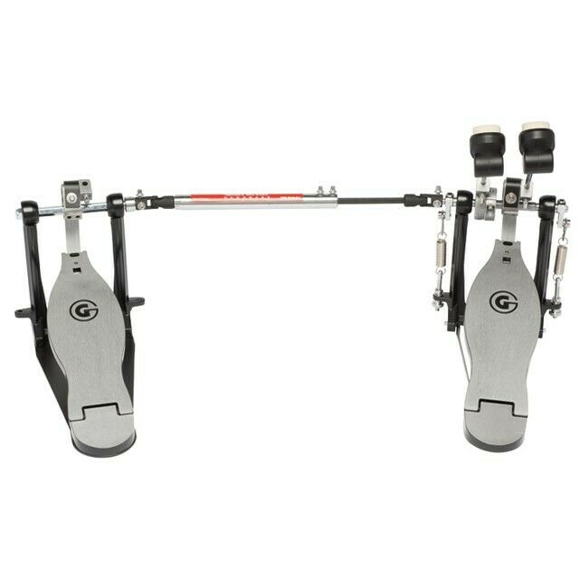
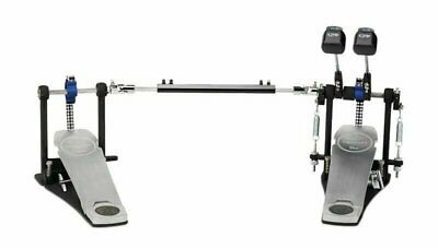
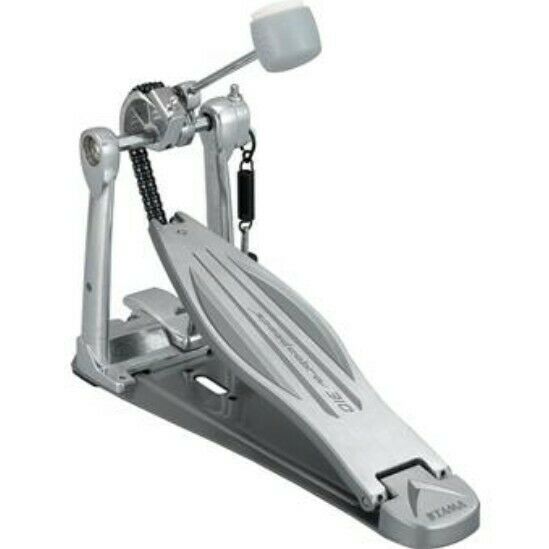
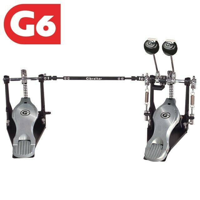
Direct drive 25" Long board single Drum Bass Pedal Carbon fiber
$ 131.99
- Description
- Size Guide
Description
Directly drive 25" Long board Carbon fiber single drum pedalMaterial: Carbon fiber with aluminum Made by CNC
Pls review this video via this link: https://youtu.be/YQj1_gPjFKI
Drum beaters
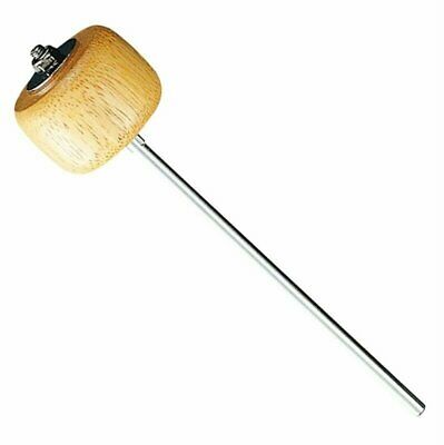
In standard-made drum pedal the shaft of the beater is made of aluminum with changeable head made of laminate (4) – Picture 1.1. Special key, added to the set, is for changing the heads – Picture
1.2.
The
structure
of
drum
beaters
enables
regulation
of
the
angle
of
drum
beater
head inclination
in
all
planes
because
the
body
(1)
is
mounted
on
ball
bearing
(2)
–
locking
it
on
the required position is executed by unscrewing the screw (3) on the rear part of the body (1) – Picture 1.1. Screw on the end contacting with ball bearing has a cavity with the same diameter as bearing thanks
to
this,
high
fastening
force
can
be
achieved
at
relatively
low
screw
clamping
force.
Both elements – screw and bearing are hardened. It prevents from any wearing of these elements. Drum beater rods are made of extra fine steel and have a standard diameter. So it is possible to use drum beaters from other manufacturers.
Drum beaters bearing
In
most
constructions
on
the
market,
drum beaters
are
usually
mounted
on
the
axes with bearings and supported on one side. This kind of solution triggers generation of bending forces during pressing
the
pedal by
the
foot.
These forces
are
the
cause
of
majority
of
bearings
damages. Our solution
eliminates
the
adverse
distribution
of
forces.
Every
beater
holder
is
equipped
with
two bearings in a way to apply a load on bearings in the form of only radial forces. It guarantees its long-term and failure-free operation.
Drum beater bearings in main beater
Our construction distinguishes itself
with the symmetric spacing of drum beaters against the bass drum axis what has the significant meaning during the bass drum sound amplification. Thanks to that kind of spacing, the sound from both
drum beaters is identical. The significant condition is well tuned equipment and good drummer. Position of the whole set against the bass drum as dependent on the configuration of clamping arm (1) and central base (2) Picture 1.2.1. in main pedal. It doesn’t matter if its DOUBLE, 2xSINGLE or SINGLE, we always configure it properly. In the situation when we play it alternately – on 2xSINGLE or DOUBLE, and we want our beaters in single pedal to hit exactly the centre of the central and we also want to have a constant symmetric spacing, we would have to configure these elements on our own – description is provided in p. 5.2 Fixing the twin drum pedal – Twin and in p. 5.3 Fixing the single drum pedal – Single
Beater’s angle of inclination adjustment
The beater holder (1) is fixed on the spring holder (2) equipped with bearings and is equipped with a scale cut out on the circuit thanks to which it can be adjusted with high precision. To do that, you have to loosen the tightening screw (3), set the beater holder at the requested angle and tighten the screw again – Picture 1.3.1. The adjustment is carried out really fast and the number of possible combinations is really big – everyone can find his own suitable settings.
Spring tension system
In
most
of
the
drum
pedals
on
the
market
a
spring
adjustment
causes
difficulties,
not mentioning
about
keeping
the
constant
spring
tension
during
a
long
playing
session.
Slackening counter-nuts, adjusting screws deflection during springs operation, creaking, etc. We eliminated all of these problems thanks to the unique construction of the tensioner – Picture 2.1. The whole tensioner construction is patented. Spring tensioner was designed in a way to make the springs adjustment an easy task and, above all, to enable verifying the spring tension in particular situation and what is the most important thing – to make a possibility of reverting to the earlier settings after the adjustment, what often takes place during equipment testing. To do that, the tensioner mechanism was quipped with a scale cut out on a stand and tensioner. Al you need to do is to note the positions suitable to us and revert it every time we want and with full guarantee of repeatability
Spring tension adjustment
To adjust the spring tension all you need to do is to push a tensioner block (1) with your hand – Picture 2.1.1 – the adjusting screw (2) will go down, and you can adjust it from now on. If the block is not forced, no adjustment is possible because the screw is locked with two resisting balls (3) placed under the adjusting screw holder (4). (picture 2.1.1 is pictorial, in reality – the adjusting screw doesn’t have to be lowered so much – situation in which the resisting balls are not placed inside the cavities in adjusting screw, will to the job). After the adjustment and when the pressure is released, screw will go
up
and
lock
in
resisting
balls
–
Picture
2.1.2.
which,
thanks
to
the
spring
tension,
will
fix
the adjusting screw in
the required position.
There are
no counter-screws or any other fixing elements. We guarantee that the spring tension will keep the same level up to the next adjustment.
Replacement of spring
To replace the spring, you have to follow the instructions below – Picture 2.2.1
•
Completely loosen the spring (1) fixed in pedal with the adjusting screw (2)
•
using the 1.5mm Allen wrench, unscrew the screw (3) on the spring suspension (4)
•
dismount the “old” spring
•
suspend the lower hook of the “new” spring on the lower spring slide suspension (5)
•
place the upper hook inside the upper suspension notch (4)
•
screw in the screw again (3)
tension the spring according to p. 2.1 Spring tension adjustment
7
Footboard
Footboard (1) is made of high-quality aluminum and is equipped with an ending (2) used to
join the pedal with the yoke (3). There are four ball bearings – two pieces for each bearing mounting
(4), which is screwed to the base (5) – Picture 3.1. This construction is very resistant to pressure and
bending of the pedal from one side to another, what prevents from clearances so often occurring in
majority
of
constructions
on
the
market.
Picture
below
shows
a
standard
engraving
–
on
Client’s
request we make non-standard designs. To order this, please contact us on our e-mail address.
Yoke – direct drive
Yoke (1) –
Picture
3.1.1 is
equipped
with
two movable
elements joined with each
other by
only one screw (2). Thanks to three holes it is possible to change its length up to 22mm. This kind of
adjustment enables to easily lower the pedal without
any
necessity of changing
any
other settings.
Both ends of the yoke are equipped with bearings.
Pedal’s height adjustment
Pedal’s height is changed by changing the active yoke length (1) Picture 3.1.1. To do this, you
have to unscrew the screw (2) which locks the yoke. Next, put it into the other hole and screw it in
again to achieve
the suitable pedal’s height.
If
the height
doesn’t
suit you, it can be re-adjusted by
adjusting the yoke holder (3). To do this, you have to loosen the screw (4), shift the yoke on spring
holder (5) and tighten the screw (4). You have to remember that in the first method of adjustment,
we
don’t affect
the
operational characteristic of a drum pedal,
but
in the second
method,
we also
change
the
arm length
of the
force
arising
from
the
feet pressure
transmitted
to pedal
–
in
other
words, the bumper striking force is changed.
Change of pedal action
In our drum pedals, we used the
4-grade transmission
adjustment of the
beater movement
against the pedal movement. Thanks to screwing down the screw (1) – Position 3.3.1 into one of the
four holes in yoke holder (2). A
position closest to the
yoke axis of rotation
gives the shorter pedal
shift and fastest beat, and the furthest position trigger the longer pedal shift and higher beating force.
A shaft connecting the main and auxiliary pedals is equipped with cardan joints win which the
torque transmission
is
carried out by
a ring
placed outside the knuckle – circumferentially –
Picture
4.1. All the elements are
made of aluminum
and
every knuckle is
equipped with 2 rolling bearings.
This kind of solution enables to transmit forces larger than in hinges with drive-transmitting element
placed in the middle of the knuckle, and prevents from any clearances during hinge operation.
Both ends of the connecting shaft are ended with cardan joints, which are equipped with set
screws (1) – 2 screw per one joint – Picture 4.1.1, used for fixing it to the main and auxiliary pedal
Connecting shaft length is adjusted by unscrewing two set screws (2), adjusting the shaft to a
suitable length and tightening the screws. Length can be adjusted up to 190 mm against the minimum
length (before unscrewing) – Picture 4.1.2
Attention!!! Care should be taken to set the tightened elements in the correct
position against each other in a way that the ends of two set screws (2) are in contact
with surfaced made on the connecting rod (3).
Connecting shaft installation DOUBLE
To install a connecting shaft in double bass drum pedal, position both pedals – main on the
right and auxiliary on the left side, preferably in parallel. The distance between them should be close
to the required a connecting shaft length. To install the a connecting shaft, insert the pin-stocks (2)
and (3) – Picture 4.2.2 and 4.2.3 of both pedals into the knuckle holes and tighten the four set screws
(1)
Attention!!! Care should be taken to set the tightened elements in the correct
position against each other – Picture 4.2.2 and Picture 4.2.3 in a way that the ends of two
set screws (1) are in contact with surfaced ma
de on pin-stocks (2) and (3)– it is vital for
correct connecting shaft operation and cooperation between main and auxiliary pedals.
If you need the more pictures or video, Pls contact to us
Shipping:
Once payment has been confirmed, your item
will be shipped within 2-3 business days.After the packages are shipped, the seller will provide the tracking number to the buyer. Normally it takes about 3-8days to arrive.
Shippment:
If you can are from South American or other, Pls contact to us . Once payment has been confirmed, your item will be shipped within 2-3 business days.After the packages are shipped, the seller will provide the tracking number to the buyer. Normally it takes about 3-8days to arrive.
Terms of Sale:
If you are not happy with any item, please contact us within 14 days of receipt so that we can arrange for an exchange or refund. After getting the returned item,we will refund the customer at the item’s price.You will pay a 25% restocking fee.
Contact us :
We are always willing to help and if you need any advice pls feel free to email.


